| |
|
|
|
| |
|
Recycle reactors are used when the reaction is autocatalytic, or when
it is necessary to maintain nearly isothermal operation of the reactor or to promote
a certain selectivity. They are also used extensively in biochemical operations. To design recycle reactors, one simply follows the procedure
developed in this chapter and then adds a little additional bookkeeping. A schematic
diagram of the recycle reactor is shown below. |
|
| |
|
|
|
| |
|

|
|
| |
|
|
|
| |
|
The recycled stream is drawn off at point Q and merged with the fresh
feed at Point P. We shall define the recycle parameter R as the moles recycled
per mole of product removed at point Q. |
|
| |
|
|
|
| |
|

|
|
| |
|
|
|
|
Two conversions:
Xsand X0
|
|
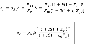
Two conversions are usually associated with recycle reactors: the
overall conversion, X0, and the conversion per pass, Xs
: |
|
| |
|
|
|
| |
|

|
(CD5-88)
(CD5-89) |
| |
|
|
|
| |
|
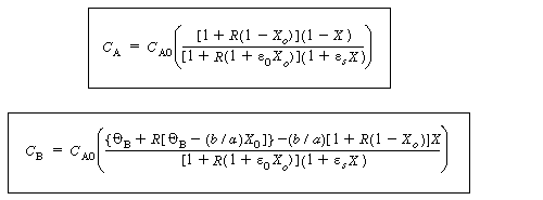
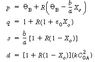
The only new twist in calculating reactor volumes or conversions
for a recycle reactor is a mole balance at the stream intersections (points P and
Q) to properly express the species concentrations as a function of conversion. Consider
the gas-phase reaction

occuring in our reactor. Let X be the conversion of A in the reactor
per mole of A fed to the reactor. The design equation is
|
|
| |
|
|
|
| |
|

|
|
| |
|
|
|
| |
|
Then: |
|
| |
|
Design equation: |
|
| |
|

|
|
| |
|
|
|
| |
|
Rate law: |
|
| |
|

|
|
| |
|
|
|
| |
|
with  |
|
| |
|
|
|
| |
|
Stoichiometry:
1. From the definition from the overall conversion, we can define
F A3 and F
B3 leaving the system, |
|
| |
|
|
|
| |
|

|
(CD5-90)
(CD5-91) |
| |
|
|
|
| |
|
From the definition for conversion per pass, we can define F
A2 and F B3
leaving the reactor, |
|
| |
|

|
(CD5-92)
(CD5-93) |
| |
|
|
|
| |
|
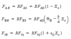
2. From the definition for the recycle parameter, R, we can define
F AR and F
BR and the total molar flow rate
in the recycle stream, F tR |
|
| |
|
|
|
| |
|
|
(CD5-94)
(CD5-95)
(CD5-96) |
| |
|
|
|
| |
|
where |
|
| |
|

|
|
| |
|
|
|
| |
|
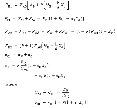
3. From the balance on the stream intersections, we have |
|
| |
|
|
|
| |
|

|
(CD5-97) |

![]()


![]()
![]()
![]()


![]()



 (CD5-110)
