Oxygen is necessary for all aerobic fermentation (by definition) [cf. Equation (7-98)]. Maintaining the appropriate concentration of dissolved oxygen in fermentation is important for the efficient operation of a fermentor. For oxygen-limited systems, it is necessary to design a fermentor to maximize the oxygen transfer between the injected air bubble and the cell. Typically, a fermentor contains a gas sparger, heat transfer surfaces, and an impeller, such as the one shown in Text Figure 7-18 for a batch reactor. A chemostat has a similar configuration, with the addition of inlet and outlet streams.
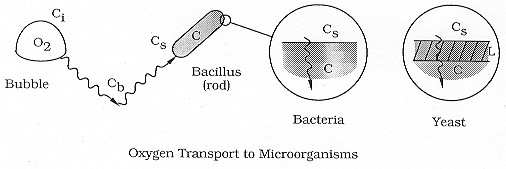
Transport Steps. The overall transport mechanism of oxygen to a cell is very similar to that described for reactant gas in a slurry reactor and as shown in Figure CD7-3. The corresponding oxygen transport and reaction steps and equations are analogous to the slurry reactor transport steps discussed in Chapter 12, that is:


(R7.2-1)
(R7.2-2)
Generally, the diffusional resistance from the bulk liquid to the cell surface
is ignored. However, depending on the cell size or cell floc size, the transfer
step from the bulk liquid to the cell surface may be rate-limiting; one
such example is the oxygenation of a culture of Streptomyces niveus.
The transport of oxygen into a cell occurs by different mechanisms for yeast
and bacteria. In the case of yeast, an oxygen molecule diffuses across an
inert cell membrane before being consumed by the cell. The corresponding
rate equations are:
Analogous to slurry reactor steps

Figure R7.2-1
Oxygen transport to microorganisms.

(R7.2-3)
(R7.2-4)
ac = cell surface area per mass of cell, m2/g
De effective diffusivity across the cell, m2/s
L = thickness of cell membrane, m
Cc = concentration of cells, g/ m3 (analogous to m in a slurry reactor, Text Chapter 12)
Ci, Cb, C0, Cc = saturation, bulk, external surface, and internal cell concentrations of oxygen, respectively
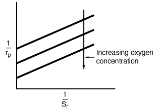
Combining Equations (R7.2-2) through (R7.2-4) and rearranging, we obtain
Yeast
![]()
(R7.2-5)
For many yeast cells, diffusion across the cell membrane can be neglected.
In the case of bacteria, the oxygen begins to be consumed as soon as it
diffuses into the cell membrane. In fact, bacteria consume oxygen primarily
at the cell membrane, where most of the respiratory enzymes are located.
As is the case of the catalyst pellet in the slurry reactor, the rate of
oxygen consumption can be given by the product of the effectiveness factor
and the rate of reaction that would occur if the entire interior of the
cell were exposed to the concentration at the external surface, C0
![]()
The rate law for oxygen consumption (uptake) generally
follows either Michealis-Menten or first-order kinetics. In many systems
it depends on the particular growth phase of the bacteria cell. Typical
respiration rates for single-cell yeast and bacteria are on the order of
100 to 600 mg O2/g cell![]() h.
For first-order kinetics we have
h.
For first-order kinetics we have
(R7.2-6)
where kr is the specific reaction rate for oxygen uptake, s-1, and h is the effectiveness factor for diffusion and reaction of oxygen inside the cell. Combining equations (R7.2-6), (R7.2-2), and (R7.2-3) gives
Bacteria
![]()
(R7.2-7)
We can observe from Equations (R7.2-5) and (R7.2-7) that at low cell
concentrations, transport steps C, D, and E (mass transfer of oxygen to and within
the cell) become rate limiting.
The main variables affecting kLab
are the impeller diameter, Di, and speed, N (rpm); volumetric flow rate of the gas, Q; tank diameter,
DT, and height LT;
and power input to impeller,![]() .
Many fermentations produce products that cause the broth to exhibit non-Newtonian
fluid behavior. Consequently, a characteristic relaxation time,
.
Many fermentations produce products that cause the broth to exhibit non-Newtonian
fluid behavior. Consequently, a characteristic relaxation time,![]() ,
is included in the correlation for the mass transfer coefficient between
the gas bubble and the bulk liquid, kLab.
Representative correlations for kLab
are given in Table R7.2-1.
,
is included in the correlation for the mass transfer coefficient between
the gas bubble and the bulk liquid, kLab.
Representative correlations for kLab
are given in Table R7.2-1.
The power input to the fermentor without gas bubbles present (![]() )
is a function of system variables:6,7
)
is a function of system variables:6,7
![]()
where the Reynolds number for this system is defined as
![]()
(R7.2-8)
When gas is present, the power input, Pg is reduced
for a given propeller speed 8
and is a function of gas flow rate, impeller speed and diameter, and the
Reynolds number. The ration of the power input with gas present, Pg, to
that without gas present (![]() )
is
)
is
![]()
(R7.2-9)
1. Low-viscosity broths Van't Reit (1):
| Range |
|
| Pure Water |
2-2600 dm3 |
Electrolytic (Solutions) |
2-4400 dm3 |
where
|
2. Non-Newtonian correlations
(R7.2-10)

(R7.2-11)

(R7.2-12)
Other parameters in the correlations are:
g = gravitational acceleration, m2/s |
|
|
|
|
|
|
|
|
N = impeller rotation speed, s-1 |
|
|
DAB = diffusivity, m2/s |

(1) K. Van't Reit, Fund. Eng. Chem. Proc. Des. Dev., 18, 357 (1979)
(2) J.F. Perez and O.C. Sandall, AIChE J., 20, 770 (1974)
(3) H. Yagi and F. Yoshida, Ind. Eng. CHem. Proc. Des. Dev., 14, 488 (1975)
(4) V.R. Ranade and J.J. Ulbrecht, AIChE J., 24, 796 (1978)
(5) D.W. Hubbard, L.R. Harris, and M.K. Wierenga, Chem.Eng. Prog., 84(8), 55 (1988)
(6) D.B. Mills, R. Bar, and D.J. Kirwan, AIChE J., 33, 1542 (1987)