THE ACROPHOBIA
VIRTUAL REALITY PROJECT
Treating Acrophobia Through a Computer Generated
Simulation of Graduated Exposure
A Continuation of the Acrophobia
'96 Project
Engineering 477: Principles of Virtual
Reality Fall 1997
F I N A L
P R O J E C T
R E P O R T **
P R
O J E C T M
E M B E R S
G R
E G H E C H T
Undergraduate, Computer Science
P H I L I
P KIM Undergraduate,
Art and Design
S
A M R A U C H Graduate, EECS
X
I A O L O N G Z H A N G
Graduate, SI
F A C U L T Y A D V
I S O R
D
R . M I L T O N H U A N G
Department of Psychiatry
A C R O P H O B I A
Back to Top.
"A person suffering from acrophobia experiences a pervasive
fear of heights that may interfere with their ability to do even the
most mundane tasks (e.g., they may not be able to park on the upper
levels of a parking structure or even walk up a flight of stairs).
A number of sensations and feelings can trigger this fear: seeing
the tops of trees from a high elevation, seeing a bird flying below
them instead of above, realizing how close they are to an open space, going
up in an elevator and anticipating the height, etc." (Taken
from Acrophobia '96 report)
T R E A T M E N T
Back to Top.
"An effective treatment for acrophobia is a technique called
"graduated exposure", whereby the patient is confronted with a series
of anxiety-provoking situations, each more challenging than the last.
So, in treating an acrophobe, a psychiatrist might take the patient to
the second floor of a building and make them look out the window, thus
exposing them to their fear. Once their fear of the second floor
is gone, the patient is moved up to the next floor. And so it might progress,
with the patient slowly moving up from floor to floor, each time waiting
for their fear to disappear. At the University of Michigan Department
of Psychiatry, such exposure treatments are performed in the east elevator
area of the main hospital. The hospital is nine stories tall,
providing a sufficiently strong anxiety-provoking stimulus for most patients."
(Taken from Acrophobia '96 report)
The East Elevator
site is shown here on this map of the UM Medical Center
area. Note that the view from the East Elevator includes four nearby buildings
and a courtyard. In the distance, areas of UM's central campus can
be seen. |
|
W H Y V
I R T U A L R E A L I T Y ?
Back to Top.
"The UM Hospital Department of Psychiatry (DoP)
would like to investigate the feasibility of using virtual reality
models to treat acrophobes. Eventually, they plan to conduct
a study which compares patients' physiological (e.g., heart rate) and psychological
(e.g., assessment of fear) reactions to the real and virtual environments.
The results of such a study would contribute to the
knowledge of acrophobia in general. In addition, if the virtual
environment could be used in graduated exposure treatments, the following
benefits might be realized:
-
Time/Convenience. The virtual reality equipment could be
stored on site at the Department of Psychiatry, eliminating need to travel
to the East Elevator location. Normal elevator passengers would not be
disturbed by acrophobes undergoing graduated exposure treatment.
-
Confidentiality. Because patients could receive therapy while
in the office, they would not have to sacrifice confidentiality as they
do when using the public East Elevator.
-
Control of the Environment. The doctor can easily control
the virtual environment - He cannot control the actual environment which
is subject to unexpected situations (e.g., imagine an elevator malfunction!).
This would allow the doctor to more easily control the progression of the
treatment, as well as to investigate which perceptual cues are most influential
to the fear. Cues could be added to or subtracted from the environment
methodologically while acrophobes' physiological responses are monitored.
-
Less intimidating. Patients may be more willing to try the
virtual environment because they know they are safely planted on the ground."
(Taken from Acrophobia '96 report)
T
H E A C R O P H O B I A V I R T U A L
R E A L I T Y P R O J E C T
Back to Top.
PAST WORK: ENG 477
FALL 1996
Back to Top.
In the Fall term of 1996, a group of 9 students developed
the first phase of the Acrophobia Virtual Reality Project in Engineering
477: Principles of Virtual Reality. Their work resulted in a VR model
of the University Hospital's east lobby, an elevator and the surrounding
courtyard in VRML version 1.0. In developing the
final VRML environment, this group created detailed AutoCAD
models and utilized software packages such as WorldUp and 3D
Studio to combine and export to VRML. In the process,
they left behind 580 files of 17 different file-types (3DS, DWG, DXF,
MLI, BMP, GIF, EBS, IV, JPG, MAT, NFF, RGB, TGA, TH, UP, WAV, WRL),
with minimal documentation.
OBJECTIVES FOR ACROPHOBIA TEAM
1997
Back to Top.
The Fall 1997 team set out to continue the
work of the previous group with the following goals in mind:
-
Upgrade the model to VRML 2.0 and prepare it for use in the CAVE.
-
Consolidate the hundreds of files left behind by the previous team's work.
-
Create a clear road map of files, formats and development strategies.
Since future work will be done on the Acrophobia project, this will allow
for a greater understanding of the various files types.
-
Incorporate scripting and interactivity into the model. This includes
opening and closing elevator doors, selecting floors by pushing buttons
in the elevator, moving the elevator up and down in response to button
pushes, adding sounds such as floor announcements, and introducing birds
and other moving elements into the courtyard. Scripting functionalities
were not available in VRML 1.0.
-
Introduce collision detection to prevent the patient from "plummeting"
out of the elevator.
-
Reduce polygon count for speed and efficiency without loss of realism.
-
Increase realism of smaller details: lighting, textures, additional world
elements.
OUR PLAN OF ACTION
Back to Top.
(Original project proposal
- '97) The work was divided into five sections: the courtyard model,
the lobby model, the elevator model, the control panel model, and scripting.
The work was tightly integrated as the models needed to be properly aligned
with each other in the VRML environment, and the scripting depended
upon the creation of particular objects in the model.
Before any work could be done, however, the tedious
task of sorting through all the files from the previous group's work needed
to be accomplished. Each file was examined
and determined whether it was actually used in the final model. Many
of the suffixes were specific to an application
that was no longer used. Ultimately, of the 580 files, 20 were actually
used for the courtyard model, 5 were used in the lobby, and 2 were used
in the elevator (this left 553 unnecessary files), including texture
maps. These files were moved to a separate directory, and became
the 'base' files on which this term's work was done.
T H E V R
M O D E L
Back to Top.
OVERVIEW OF THE MODELING
PROCESS
Back to Top.
The process followed was a little different for each portion of the
model, but in general, this is the process that was followed in creating
the VRML2.0 model.
-
Update AutoCAD models
-
Fix geometries
-
Add new objects
-
Name the various objects consistently and meaningfully
-
Aesthetic manipulation
-
Import AutoCAD models into 3DS
-
Add textures, colors, and lighting
-
Create simple animations
-
Integrate some subsets of the AutoCAD models
-
Scripting
-
Export 3DS models to VRML2.0
-
Add more complicated animations and scripting through direct editing of
VRML2.0 files
-
Integration
-
Import VRML2.0 models into CosmoWorlds to correctly place
the various sub parts and create the final VRML2.0 files
The sections below which address each portion of the model give more specific
details about what was done in the creation of the various parts.
THE COURTYARD: THE WORLD
OUTSIDE
Back to Top.
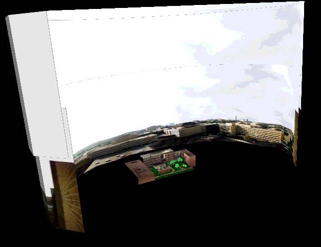
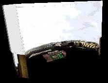
The Panoramic View
In addition to the 3D buildings in the courtyard,
the surrounding world needed to be rendered in a panoramic manner to convey
a sense of realism. The previous group simulated the far buildings
and the horizon by wrapping a panoramic texture map image onto a parabolic
surface. This was lined up with a viewpoint from the elevator.
An image of this is shown below.
While this initially appeared convincing, it was
not ideal. First, the panorama contained the same buildings that
were being rendered as part of the courtyard. This reduced believability
for the astute viewer since images were redundant. Also, the parabolic
surface contained a considerable number of polygons. At the start
of this year's project, it was thought that the panorama could be created
using VRML2's background node. However, since
the world was placed at the center of the background cube, positioning
was difficult and the viewpoint from the elevator lobby looked odd.
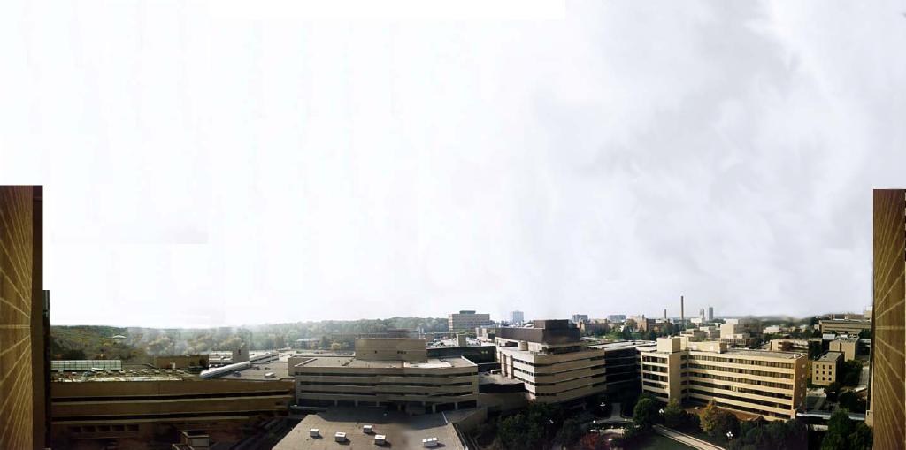
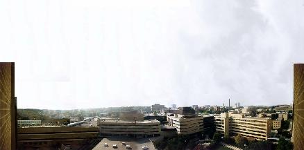
Ultimately, a panoramic shape similar to the original design was created.
Taking two partial cylinders and applying a texture map of the horizon
proved to retain visual effectiveness and reduce the number of polygons.
 The
old panorama, with a parabolic surface
The
old panorama, with a parabolic surface
The new panorama, with a cylinder-like surface
The snapshot below shows the horizon used on the backdrop.
The Courtyard and Near Buildings
The courtyard and adjacent buildings needed to be
modeled at a closer distance in order to create motion parallax from the
viewpoint. As the viewer changes position at the window, his view
changes, and motion parallax is evoked. Simulating this motion parallax
was important in order to give the viewer the perception of depth and height.
The previous group created a planar grid and curve
for the courtyard lawn and sidewalk. For the nearby buildings, flat
planes were created and each saved in separate 3DS files.
These files were named with the numbers 1 through 14. No documentation
was left as to which plane represented which building. This term,
in order to consolidate files and create a more usable world, those 14
planes and the lawn and sidewalk were combined into a single AutoCAD
model. Unfortunately, though not surprisingly, the scale of the lawn
and that of the buildings was different; and much time was spent trying
to find the correct ratio of sizes. In order to create the buildings
which would receive texture maps, surfaces were then applied to the planes.
The textures were applied in 3D Studio; but the translation and
rotation of the textures was often incorrect, requiring adjustments by
hand.
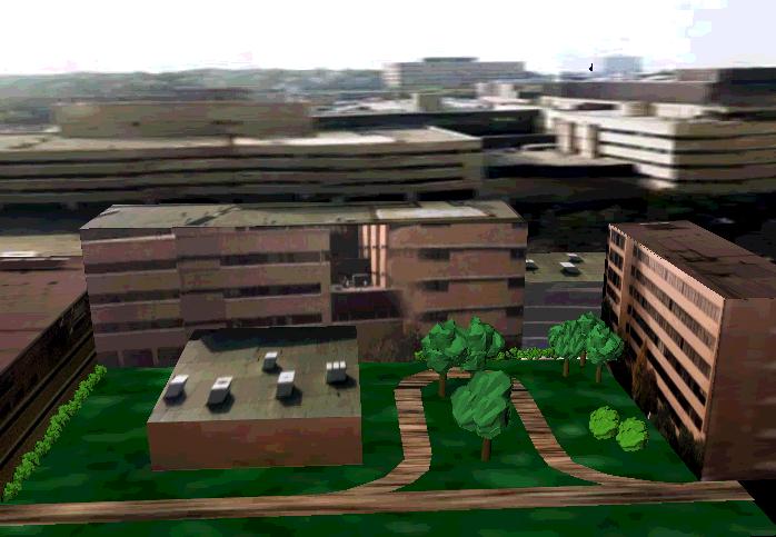
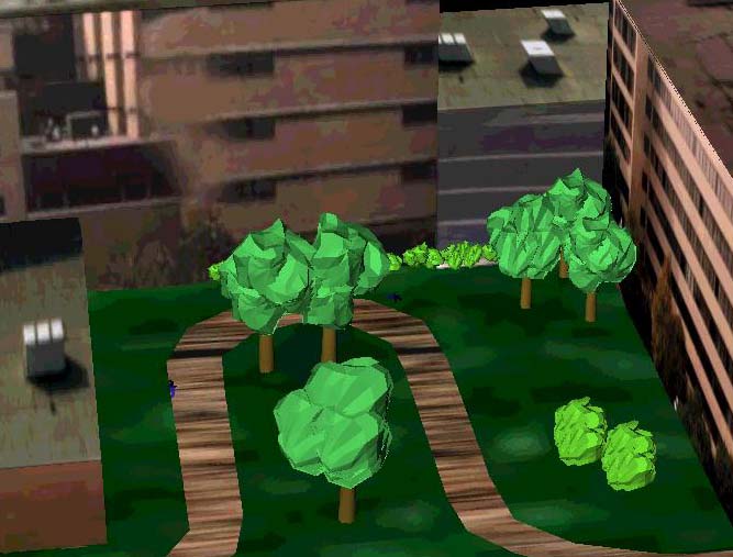
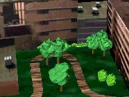
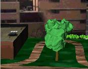
Originally, the only additional elements in the courtyward
were images of trees mapped onto rectangles. This was a good attempt,
given the capabilities of VRML 1.0, but looked unconvincing as the
user moved up the floors of the building. We felt that a three-dimensional
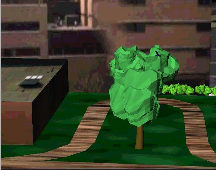
solution would be more convincing. Trees were created in 3D Studio
by overlapping several twisted and warped spheres and placing them over
another distorted cylinder for the trunk. Bushes were created by
scaling down the tops of the trees. This created nice looking 3D
objects in the courtyard that were viewable from any angle, and had depth
that showed in the reflective nature of the sphere's contours. The
downside in using this method is that it requires a multitude of vertices
to define the plants, which slows down the model on less powerful machines.
Several trees and rows of bushes were included.
To increase the realism and the sense of height,
birds were added that fly around the courtyard. These are inlined
worlds that create and translate polygons in the shape of a bird flying
in a circle. They were taken from the "Tenochtitlan" VRML
world at http://vrml.sgi.com/handbook.
A few birds were placed near ground level. Others were placed at
higher elevations in order to be seen from the upper floors of the building.
Another minor adjustment was made to the lawn of
the courtyard. The previous group used a texture map that was green,
but contained many specular highlights that made it look like something
other than grass. Photoshop was used to darken and smear this texture
to create a more aesthetically pleasing surface. A texture map of
dirt was applied to the sidewalk, but at present is not satisfactory in
appearance.
 The old virtual courtyard
The new virtual courtyard
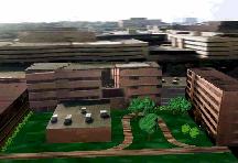
Detail views of the new courtyard
T H E L O B B Y
Back to Top.
The elevator lobby was created using the
model constructed by the previous group. This model was quite well
done in that its architecture properly resembled that of the actual site.
Therefore, rebuilding the entire lobby was determined to be unnecessary.
It was imported into AutoCAD R14 and minor adjustments were made
so that all the geometries were in proper alignment. Moreover,
the model was edited to insure that all appropriate objects were solids
and consistently named for use in 3DStudio. Extraneous elements
such as a highly detailed plant were eliminated from the AutoCAD
model since it increased the polygon count and obstructed the view of the
window where the acrophobic patient would look outside. The lobby
was then further modified in 3D Studio Max. Textures
from the old model were not authentic to the actual site. Therefore, photographs
of the walls, ceilings, signs, and buttons were taken and manipulated using
Photoshop. These textures or their colors were used in 3D
Studio to create a more true-to-life model of the lobby.
The final touch was that of lighting, also done in 3DS.
Lighting contributes greatly to the level of realism in the model since
it gives tonal variations and shadows to the many surfaces.
 Actual
lobby
Actual
lobby
Old virtual lobby
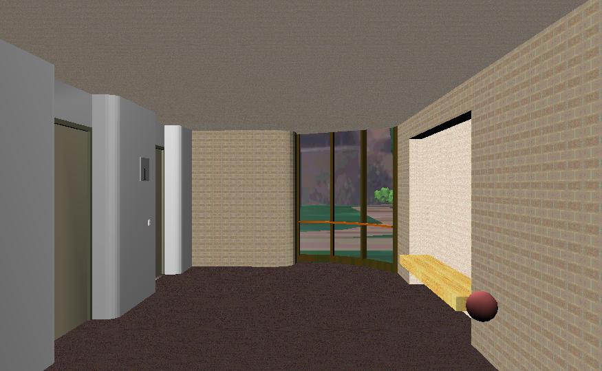
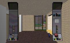
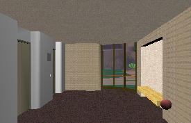 New
virtual lobby
New
virtual lobby
ELEVATOR
Back to Top.
The elevator was remodeled using AutoCAD
and 3D Studio Max. While the actual scale and detail
of the older elevator were convincing and accurate, problems with this
model occurred when portions of the paneling and exterior frame did not
render completely in updated versions of the various applications.
By using parts of the older model as a template, a new elevator was constructed
in AutoCAD R14 and further modified in 3DS MAX.
This proved to be the most effective method of modeling for two reasons:
The elevator made by the previous group was constructed with great precision,
and it needed to fit seamlessly with the other preexisting elements.
In addition, since the older textures of the elevator did not match the
real elevator, new images of the real location were then taken, manipulated
in Photoshop and added to the model. As with the lobby, the various
geometries in AutoCAD were re-named in such a manner that they could
be easily recognized when imported into 3DS.
Two control panels were to be placed in the elevator.
The previous group had constructed a realistic copy of the actual control
panels at the University hospital, and they are used in the present model.
The various geometries in this model were also meaningfully renamed for
use in 3DS. While we eliminated some elements, on the whole,
the panels were used with their original geometries. Numbers for the various
floors were added on the side of each button, as well as a viewing panel
that identified the floor where the elevator stopped.
Textures were then added from pictures of the actual control panel to extend
its level of realism. (NOTE: Images of the control panel are included
in the section on the new pop-up control panel.)
 The
old virtual elevator
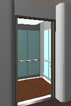
The
old virtual elevator
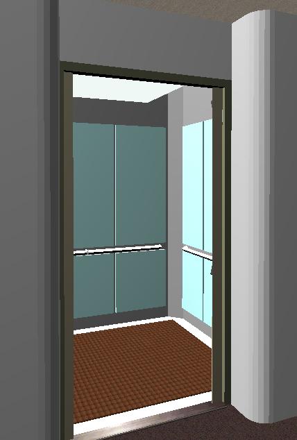
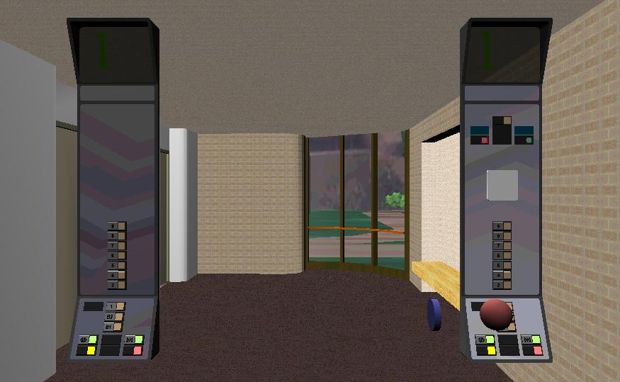
The new virtual elevator
POP-UP CONTROL PANEL
Back to Top.
In addition to the control panel situated permanently
in the elevator, another set of controls were created in order to allow
the user to access the functionality of the elevator outside the physical
confines of the elevator. This control panel is activated by pressing
on a red sphere, which pops up an exact replica of the elevator control
panels. These panels then follow the user throughout the environment.
This allows a user to move outside the lobby and elevator, where they can
get an overview of the whole model, and still control the elevator.
(NOTE: The images below include an image of the old control panel that
was not a pop-up object!)
 The
actual control panel
The
actual control panel
The old virtual control panel
 The
new pop-up virtual control panel
The
new pop-up virtual control panel
INTERACTIVITY AND SCRIPTING
Back to Top.
The original Acrophobia group created the model with the intention
of adding interactivity to it. They created all the appropriate control
objects, like the floor buttons in the elevator, but were limited by the
capabilities of VRML 1.0. This time, we had the added benefit of
access to VRML2.0 and were able to add much of the originally intended
functionality. The scripting added to the model falls into 3 major
areas: Elevator Controls, Pop-up Control Panel and Miscellaneous.
-
Elevator controls
-
Floor buttons: The floor buttons were scripted to respond as much
like an ordinary elevator as possible. The user can select a destination
floor by pushing the appropriate button and the elevator will move to the
appropriate floor. Upon arriving at the given floor, the model is
updated to reflect the current floor, by changing such things as the floor
markers on the the wall and the control pane. Scripting this interaction
proved to be a minor challenge as the movement of the elevator is related
to both its current position and the intended destination. The details
of the floor movement script were initially worked out using simpler models
with only a few relevant objects, and later incorporated into the larger
VRML2.0 world.
-
Open and close buttons: The doors of the elevator can be opened
by pushing on the "up-down" button in the lobby and opened or closed by
pushing on the appropriate buttons in the elevator.
-
Sounds: All of the elevator interactions have associated sounds
which increase the reality of the experience. A voice in the elevator informs
the user whether the elevator is moving up or down and tells them what
floor they have stopped at. The doors also make appropriate sounds
when opening or closing.
-
Pop-up Control Panel
A pop-up control panel that follows the user around was added to the
VRML2.0 model. It can be toggled on and off by clicking on the little
ball that follows the user around in the lower right. This pop-up control
panel has all the functionality of the control panel in the elevator. When
the pop-up control panel is turned on, it can be moved closer to or further
from the user by dragging the mouse over a little blue cylinder that appears
near the sphere.
-
Miscellaneous controls
A couple of interesting miscellaneous controls were added to the control
panel:
-
Lighting: The user can toggle the lights in the lobby on or off
by clicking the yellow button on the control panel
-
Invisibility: The user can make the walls of the elevator partially
invisible by clicking the red button on the control panel. This allows
him to see the ground moving away as the elevator goes up.
PROBLEMS ENCOUNTERED
Back to Top.
Files
Dealing with all of the inhereted files turned out
to be a rather difficult process. There was a large number of files
and little information about their contents. We had to inspect each
one to figure out exactly what it was and where it could be used.
The Previous Model
The models from the previous group were meticulously
crafted, however there were problems with the amount of detail as well
as the surface normals. Some details were seen as unnecessary, but
they were difficult to eliminate due to the fact they were parts of solids
in the AutoCAD models. Some of the surface normals were reversed
and the surfaces did not appear when imported into 3D Studio Max.
Hardware/Software
The hardware and software proved at times to be unstable
and buggy. Computers were sometimes inaccessible, due to the limited
resources in the VR Lab. We also encountered numerous problems in
trying to update files based on previous software versions and old standards.
One example is that a complete model of the elevator and lobby had to be
redone; The transition between versions of WorldUp and AutoCAD
reversed many of the normals, causing the surfaces to render incorrectly.
Other frustrations arose in making VRML2.0 files run consistently
between the SGI and NT platforms, particularly with respect to the scripted
interactivity.
Merging of VRML Models
Upon the completion of the VRML models of the courtyard,
elevator, and lobby, the worlds were merged to form the single ACRO world.
At this time, it was realized that the courtyard was approximately 3 times
the scale of the lobby and elevator. This was a difficult problem to predict:
although the elevator and lobby were exactly measured and modeled, the
buildings of the courtyard were modeled on a relative scale-done so they
look approximately correct. The differing scale only became evident when
the elevator moved up/down floors; since it was only 1/3 scale, it appeared
the elevator wasn't moiving far enough.
The first attempted solution was to triple the distance travelled by
the elevator. This made it so each floor had the correct view of the courtyard.
But ultimately, felt unnatural in the time the elevator took to travel
3x its height and in the enormous height of the trees. The courtyard was
then scaled using CosmoWorlds, making it of an equal scale to the lobby.
Problems with the avatar arose following this, as it seemed that when the
viewpoint was switched to one of the courtyard, the avatar was also scaled
down. This was solved by routing the courtyard viewpoints into an avatar
that was 3 times the size of the avatar in the lobby. This solved all scale
problems.
Texturing
Much of the lighting and texture mapping for the
VRML worlds was done in 3D Studio. For the courtyard,
it was extremely important that the texture maps line up at the edges,
so that a building's roof matches its walls. However, it was difficult
to control the manner in which 3DS created texture coordinates.
CosmoWorlds was used to correct this, but this introduced other
errors as CosmoWorlds did not recognize or read some of the VRML
nodes created in 3DS.
LIMITATIONS OF THE CURRENT
MODEL
Back to Top.
What? No CAVE?
A surprising limitation came in the realization that the development
for VRML2.0 and the CAVE were largely separate tasks.
The CAVE is still limited to VRML1.0 based Inventor files
and offers no simple means of scripting. It was decided to focus
the development on the VRML2.0 model, which is web accessible, and
should soon be readable by the CAVE system.
Performance
Our current VRML2.0 world includes many polygons, particularly in the
courtyard portion of the model. Due to this fact, it only runs well
on high-end machines.
Scripts
We were never able to resolve the problem we were having with trying
make our scripts run on both the SGI and NT machines. The current
scripts in the VRML2.0 model have only been verified to work correctly
on SGI machines running CosmoPlayer 2.0.
RECOMMENDATIONS
Back to Top.
The entire purpose of this project - immersive, phobia
treatment - is contingent on transferring the model into the CAVE environment.
Thus, it should be an immediate priority to convert the model into a compatible
format for CAVE simulation. This should be simplified in the
near future by a VRML2.0 compatible CAVE.
It would also be of use to figure out how to reduce
the complexity of the model and work out the details of writing the scripts
to work on NT machines as well as SGI machines. Reducing
the complexity would allow the model to run on less powerful machines.
We have put together a "roadmap"
of the files used in the current model. It should be of assistance
to anyone who is interested in further developing the Acrophobia project.
THE VRML MODEL
Back to Top.
You've read about it, now see it for yourself! Download the VRML
version of our model.
** NOTE: Due to the size of the model and the VRMLscripting,
this model works best on high-end machines. We have found it to work best
on SGI workstations running the Cosmoplayer plugin.
** DISCLAIMER: Some portions
of this project report were taken from the previous acrophobia group's
report, from the Fall 1996 session of Eng 477. Full credit where
applicable is given to them.
Updated on December 7, 1997 by ghecht@umich.edu
. Updated on December 14, 1997 by Philip Kim. Updated on December
14, 1997 by Sam Rauch.