
[The Lowbrows have been fortunate to be permitted to use the fine 24-inch McMath telescope for many years. Dick Sider and David Snyder are currently working on a project to document the history of The University of Michigan’s observatories. Dick Sider discovered this article on the 24 when it was still young and camped out at the McMath-Hulbert Observatory on Lake Angelus, in Pontiac, Michigan. The following is the first of a two part article. This article and the accompanying photographs are reprinted with permission granted to The University Lowbrow Astronomers c/o Bernard Friberg by the University of Michigan, Bentley Historical Library. - Ed]
from Publications of the Observatory of The University of Michigan Volume VIII, No. 6
In the fall of the year 1936, the three founders of the McMath-Hulbert Observatory - the late Francis C. McMath, the writer’s father; Judge Henry S. Hulbert; and the writer - started plans for a 24-inch reflecting telescope. By that time it had become apparent that the new 50-foot tower telescope was successful. It was thought that ultimately the original 10 1/2-inch reflector would be relieved of its share in the solar program, and that it was desirable to return to the earlier lunar and planetary program of the observatory with a more powerful instrument. This was made possible by the fact that the mounting for the 10 1/2-inch had been originally designed to carry a twenty-inch mirror.
Francis C. McMath and Judge Hulbert had been present during the pouring of the second 200-inch mirror and were much interested in the low coefficient of expansion pyrex which the Coring Glass Company had succeeded in obtaining for the great mirror. Accordingly, Mr. McMath suggested the we ascertain from the Coring Company the availability of their special pyrex for our proposed new telescope. This inquiry resulted in the purchase of a ribbed 24 1/2-inch primary mirror blank, together with the two secondaries and a plug for the optician’s use when figuring the primary.
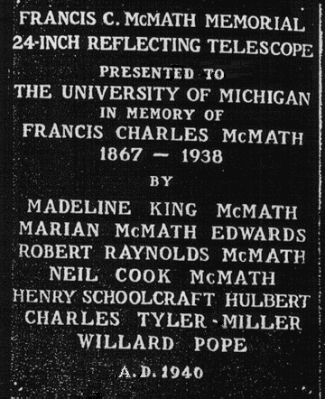
During the years 1937-38, the 10 1/2-inch and its spectroheliokinematograph were in use making simultaneous records with the solar tower; and, in 1938 especially, Sawyer and Malesky employed the instrument in exploring the methods and techniques of the prominence radial velocity program. A generous gift by Julius F. Stone in July, 1938, made possible a new spectroheliograph in the solar tower for the radial velocity program, and plans for this instrument were started the following September. This combination of circumstances made it possible for the writer at this time to suggest to his associates the idea of a memorial telescope to Francis C. McMath, who had died February 13, 1938. The new telescope was to make use of the pyrex mirror blanks purchased by the three founder during Mr. McMath’s lifetime. The names of the donors are shown on Plate 1 [see below], which is a photograph of the bronze plaque attached to the west side of the pier of the telescope.

Plate 1 - Photograph of the bronze plaque on the west
side of the pier of the 24-inch McMath telescope.
It was found, upon investigation, that the dome needed almost no alteration in order to house the new telescope. Telescope clearances were carefully laid out and, except for a rearrangement of the shutter operating cables, were found to be close but adequate. Floor clearances also were carefully studied, and, as a result, the observing floor was raised two feet, giving the observer easy access to the guiding eyepiece. A tunnel was excavated and lined with masonry in order to provide access to the hollow part of the pier, and the electrical circuits between the control room, observer’s control box, and telescope were rearranged and somewhat simplified. Practically all of the electrical equipment used for the 10 1/2-inch was also used for the new 24-inch telescope.
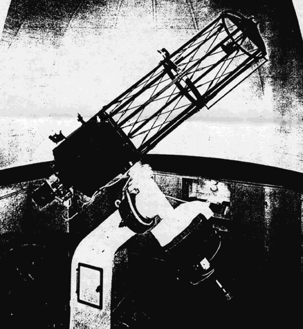
Plate 2 [see below] is a general view of the telescope taken through the open shutter of the dome. The old pier, declination axis housing, declination axis, and polar axis were retained in the new instrument, and the original declination and hour circles were again mounted as before. The remainder of the telescope is new. It was decided to provide three motions in right ascension and follows: First, a fast-setting motion of 45 degrees per minute of time; second, a slow-setting motion of 90 minutes of arc per minute; and, third, a guiding motion of 45 seconds of arc per minute. The first two of these motions, together with the slow-setting motion in declination, are controlled by push buttons located on the auxiliary control box. The 4 1/2-inch refractor which originally was employed as a guide telescope is now mounted on the 24-inch as a finder.

Plate 2. General view of the 24-inch Francis C. McMath
Memorial
Telescope taken through the open dome shutters from the east side.
The tube center section and mirror cell were built up of 3/16-inch rolled steel, reinforced with ring flanges. This entire assembly was welded together and thrice annealed before machining, resulting in a very adequate mirror ventilation. To this end, the mirror cell was provided with large ventilating holes, through which the mirror can be seen in the photograph.
In order to avoid “dead air” in the tube, the open or skeleton type of design was chosen The longitudinal struts were made of 13-gauge steel formed into box sections which extend the full length of the tube. These boxes were completely welded together and then welded to the center steel section and stiffening rings. The center circular strut, also of box section, was made in six pieces which, after individual welding, were welded between the longitudinal struts. The adjustable tie rods were added last. Altogether the assembly is unusually rigid. It may be of interest to note here that a very large lathe was used as a welding jig and that, after welding, the tie rods were adjusted while the assembly was in the same lathe. Next, the entire tube assembly was swung “on centers” in the lathe and both ends of the tube turned at right angles to the optical axis.
The secondary mirror is supported by four 3/32-inch steel webs. The end ring, and secondary center tube were assembled in a heavy jig, welded together, and annealed. After annealing, the assembly was placed in the big lathe, the center tube was bored, and all faces made true and concentric. The outer ring was fitted into a recess in the telescope tube end in order to locate accurately the secondary assembly. The resulting tube assembly has proven very accurate and rigid, and has given entire satisfaction.
The mirrors were entrusted to the Perkin-Elmer Corporation of New York City for figuring. Our Specifications were exacting, as no part of any surface could depart from the theoretical surface by more than one-tenth of a standard wave-length. Three mirrors were ordered to be made from the optical pyrex furnished by us: First, the 24-inch primary, focal length to be 96 inches plus or minus one quarter of an inch, or F:4: the diameter of the central hole to be not less than 4 or more than 5 inches. Second, two secondaries, one to give a combined focal length of 50 feet, or F:25; and the other mirror a combined focal length of 100 feet, or F:50.
Perkin-Elmer Corporation completed the primary mirror by conventional methods and it was tested at their shop by Dr. Heber D. Curtis, who pronounced it well within the specifications, Reported that it was an unusually fine surface, and recommended its acceptance. The two high magnification secondaries, however, presented real difficulties. McCarthy, of Perkin-Elmer, felt that conventional methods of testing were inadequate and proposed a new method, which he has recently described. The Perkin-Elmer Corporation made up the necessary auxiliary optical equipment, and our two secondaries were figured by the new method, which eliminates the combined testing of the primary and secondary. These two mirrors have been an unqualified success, both focal lengths being well within specifications, while the figuring is superb. Exposures for the disk of Jupiter are shorter by a factor of at least twelve when compared with our old 10 1/2-inch telescope.
We were particularly desirous of building a fine drive for the 24-inch telescope because we planned to use the 100-foot focal length combination a large portion of the observing time. Fortunately, the thermionic tube control apparatus was available, and after due consideration, it was decided to drive the telescope directly with the inverted converter in order to secure DC motor starting characteristics in winter.
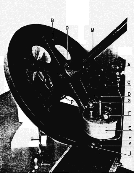
The converter can be seen at A, Plate 3, [see below] which is a photograph of the new right ascension drive assembly. At B is shown the 46-inch diameter, 720-tooth, 5-pitch LH wormwheel. The blank for this gear was made by shrinking a bronze ring over a welded and double-annealed steel built up wheel an hub. This construction was rather expensive, but the wheel will not change shape with aging; consequently, the methods was thought to be economical in the end. The firm of Hanson-Whitney furnished the worm and thrust bearing assembly, and the combined performance of these is practical perfection. The worm is of nickel steel, hardened and heat treated after preliminary machining, and finally ground to a mirror finish. The end thrust plug is glass hard high speed steel, lapped and ground, while wearing part is soft machine steel. This type of construction has been used several times at this observatory, and was suggested to the writer by Curtis several years ago. C is the 1 to 90 ball bearing worm and wormwheel first reducing gear, and its output shaft is at D. Shaft D is split inside of the aluminum cup E, permitting the slow setting motor G and the guiding motor F to superimpose their motions on the normal motion of shaft H. It should be emphasized that the gearing attached to these two motors, F and G, is not a part of telescope drive as such and is normally not in motion.

Plate 3. View of the New Right Ascension Drive.
At I is seen the end of the main worm which carries the 1 to 57 worm and wormwheel drive from motor A to polar axis M. At N can be seen a few teeth of the fast-setting gear, but the motor, being mounted on the under side of B, cannot be seen. The commutator supplying electrical current to the fast-setting motor is seen at upper D. A 50-pound weight is attached to cable R underneath the floor and is fasten to the polar axis by means of pulley wheel P. Unfortunately, due to construction considerations, the connection between the wormwheel B and the original polar axis could not be made as large as desired. This has resulted in some elasticity of the telescope as a whole, but has not affected the right ascension driving qualities of the telescope.
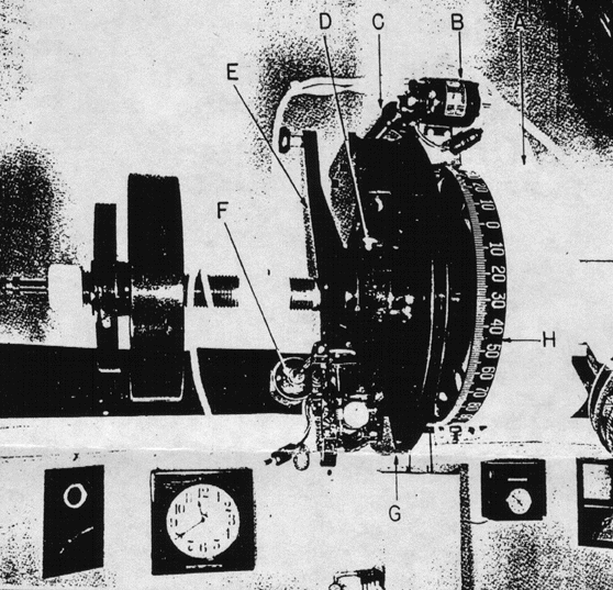
The declination drive motions are, in a sense, somewhat similar to those of the right ascension drive, since they again include coarse-and fine-setting and guiding motions, together with the straight declination drive. Fast or rough setting of the telescope is made by releasing a friction clamp, the back of which is shown at the D, plate 4 [see below] and moving the drive arm E to the desired declination angle. This angle is easily read in the declination circle H.

Plate 4 - View of the Declination Drive Assembly for the 24-inch McMath telescope.
The slow or line-setting motion of 50 minutes of arc per minute of time is obtained through the drive motor B, 9-pitch worm C, and 680-tooth wormwheel G. Worm C was made in two pieces and has a special spring adjustment in order to eliminate all lost motion at this point in the assembly. The slow motion motor support bracket A purposely is a very heavy casting to act as a counterweight about the polar axis. This was done to avoid adding to the already heavy stress imposed upon the declination axis by the new tube loading.
The slave Selsyn F transmits the guiding and drive motions from the Ward-Leonard system and gear carriage in the control room. This same system was used on the 10 1/2-inch reflector and on the second flat mirror in the solar tower, and has been described and illustrated.
Special attention was paid to the very important problem of eliminating lost motion in the entire declination drive assembly. Precision thrust and radial ball bearings were used throughout, and some form of take-up adjustment was provided at each point where normal wear might occur.