
I’ve always shied away from making refractor lenses, because the thickness requirements scared me. For a lens, the optical designer would always specify the thickness of the lens, in addition to its radius of curvature, surface finish, surface accuracy, wedge, etc. Mirrors seemed to me to be a lot easier to make.
Since I’ve been designing optics, I’ve come to understand that lens thickness is the most error-tolerant of all of the things specified, but I’ve still been reluctant to make lenses. However, all things come to those who wait.
I was recently asked to grind and polish some filters for a local medical company. Their existing filters had the wrong extinction values, and grinding them thinner was the cheapest way to get the desired values. Unfortunately, the filters were composites made of three cemented glass layers, and I had to grind down and polish one of the glass layers to the thickness of a piece of paper (0.003”), without breaking through the optical cement to the dielectric coating, or chipping or breaking that thin layer of glass.
Here is how I did it.
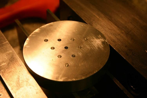
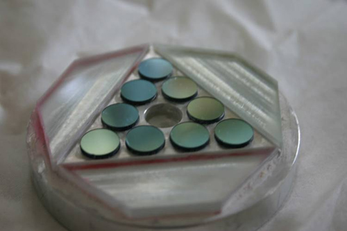
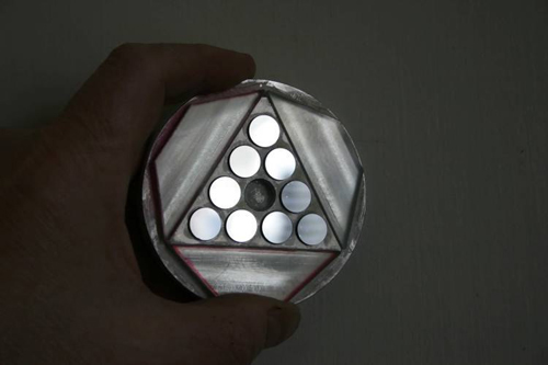
I first machined an aluminum block to hold the filters in place and at a common height, since in optics, success or failure often hinges on good tooling. The filters rested on accurately machined ledges at equal depths. They have through holes under them, so their individual thicknesses can be monitored during grinding, and so wedge can be controlled. The thickness tolerance on the filters was +/- 0.0004”.
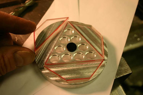
I then cut some glass blockers on a diamond saw, and used optician’s cement to glue them to the machined aluminum puck. The glass blockers keep the edges of the filters from turning down. In the above picture, a filter appears in the middle of the puck.
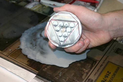
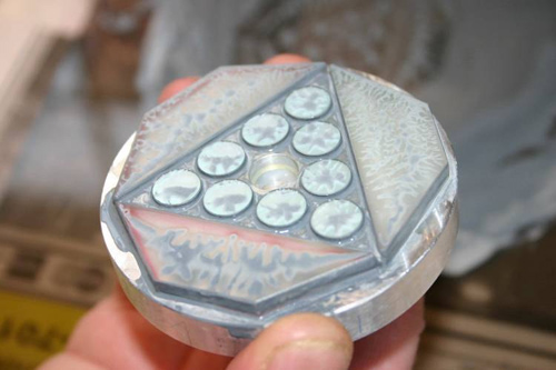
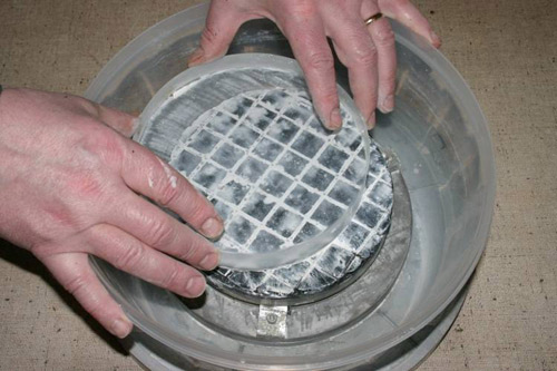
Next, the filters were glued in and were ground against a piece of scrap float glass, which is quite flat from the manufacturer.
The critical thing to know when grinding off 0.122” glass to a tolerance of +/-.0004” is how much glass is ground off by each grade of abrasive. The answer to that question involves working backwards from our desired thickness.
The idea of starting with a coarse abrasive is to be able to grind fast enough to do the job economically and in a reasonable length of time. But coarse grinding creates chips and fractures that propagate into the glass, which have to be removed by finer abrasives, which in turn leave chips and fractures of their own. This continues right up to polishing. Ideally, you’d like to grind as much glass as possible with coarse abrasive, then switch to polishing. However, you can’t polish out craters from #80 abrasive in a reasonable length of time. Therefore, I used a grinding sequence of #120, #320 (nine micron), five micron, and then polished with Zirconium Oxide.
The trick is to leave enough glass at each stage to allow the next stage to remove the fractures which grinding drives into glass, and that means knowing how deep the fractures are from each abrasive. It turns out that the fractures from each stage are about as deep as the diameter of the abrasive. Polishing compounds are composed of one micron diameter particles, and they remove a few microns of glass. Five micron abrasive leaves fractures about five microns deep, nine micron leaves nine micron fractures, and so on. I was conservative, and left more than twice as much glass on the filters at each stage as was required to clean up the fractures. At 25.4 microns per 0.001”, I left 0.0005” for polishing, 0.001” for five micron, 0.002” for nine microns, and ground the rest with #120. It seemed to work.
I poured a pitch lap on an aluminum disk, cut the facets with a couple of new razor blades (they dull and start to chip the pitch after cutting about eight channels, and so need to be changed), and pressed the lap flat with an old fused silica optical flat.
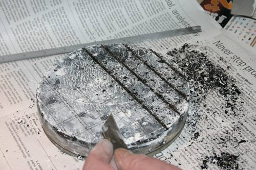
Ideally, when machine polishing with the optics on top, the lap should be 6/5 the diameter of the optic. In this case, I didn’t have a ready-made tool of the correct size, and the lap I had was considerably bigger than optimum. When this happens, you have to start polishing with a lap that is already in the desired shape. In hand polishing, the lap is often the same size as the optic, and working them together causes the lap to take on the correct shape. However, when the sizes are very different, you have to rely on some other method for forming the lap. Hence the optical flat.
Pitch is soft, and on a microscopic (optical) level, it very much resembles the seat cushions on a couch. If your optic doesn’t bridge the entire couch, it will locally sink into the cushions, and the edges of the glass will get rounded off as the optic moves across the pitch. That is the reason for having a glass blocker surround the filters, and for flattening the pitch by frequently pressing the optical flat onto it during polishing.
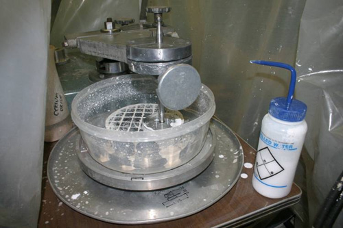
The machine polished out the filters in about twenty minutes. If I’d known they were this fast, I’d have bought a machine just to polish my first 12.5” mirror.
When the polished filters came off the machine, I checked them on a Zygo interferometer. They were flat all the way across to about 1/10 wave. However, they were still 0.0005” too thick (I had overestimated how much material polishing removed. It was, after all, the first time I tried this), so I placed a couple weights on the polishing arm, cranked the speed up, and let it go for another 40 minutes.
At the end of that time, they were at the correct thickness, but their overall surface flatness had dropped to 1/4 wave. (High pressure plowing had rounded the edges.) This is a good argument for keeping good records, or for letting someone else do the job first. However, since 1/4 wave was about four times better than the specifications required, the customer was quite happy with the results.