
[This is the second and final segment of the article on the McMath 24 inch telescope printed with permission from the Bentley Historical Library - Ed; See also the first segment of this article]

Plate 5
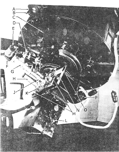
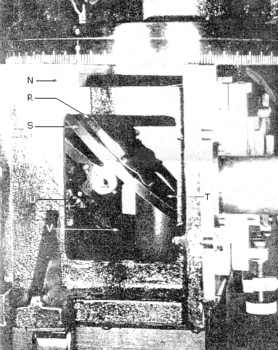
The camera end of the new 24” reflector, Plate 5, represents a rather unique departure from standard telescope design. Since this instrument was intended primarily for work on the lunar and planetary programs of the observatory, the 35 mm camera was used as a nucleus about which the driving and guiding accessories were constructed. This general design procedure has produced a dual guiding system which embodies all the features deemed most desirable by the observing staff based on several years experience experience with our particular photographic problem. The lower guiding assembly, intended for lunar or planetary work, guides directly on the central cone of light being photographed. This is accomplished by the use of the rotating shutter and mirror combination shown in the enlarged print of the camera support casting (Plate 6). S is the shutter disk carrying a semi-circular plane mirror R and the easily interchanged shutter plate T. U is the last step in the Selsyn driven gear train which operates the camera and shutter. At V is shown the small counterweight balancing the entire shutter shaft assembly.

Plate 6
During the guiding period the light beam from the secondary is reflected through 90 deg. by the shutter mirror R and comes to a focus on the illuminated reticule. The optical center of this reticule can easily be shifted by means of the adjusting screws to any chosen guiding point in the field. The reticule can then be rotated so that the guide point will follow the wires in both right ascension and declination. Extension tube G includes a 65 mm lens set for approximately conjugate foci to transfer the image from the reticle through the rotatable right angle prism F to the guiding eyepiece E.
Throughout the open-shutter or photographing period, the mirror lies outside of the central light cone and therefore reflects no image through to the guiding eyepiece. This important feature prevents the observer from shifting the telescope while a photograph is being taken. Also, since the reticle to mirror and camera focal plane to mirror distances were set accurately in our shop, the telescope can be focused at the guiding eye piece through use of this guiding system.
By shifting plate K against the stop plate O, the low power composition eye piece H is brought into the optical axis position. Here, by means of a focal plane diaphragm which is a duplicate of the camera aperture, the observer is able to view the exact field which will be photographed at the camera. This same setting can also be obtained on a ground glass placed at the camera focal plane, but this latter procedure requires the removal of the camera from its mounting.
The second guiding system is intended primarily for lunar and stellar work. The guiding eye piece assembly--made up of the illuminated reticule, transfer lens, right angle prism, and guiding eye piece previously described--is slipped out of its bayonet lock on the plate K and moved to a new position at D. Flange D is part of an adjustable tube which carries a small reflecting prism at its opposite end. This prism, together with the eye piece assembly, can be moved radially, by means of the adjusting screw, from the outer edge of the cone of light coming through the central hole in the primary, to the edge of the inner central cone being photographed. The entire assembly can also be revolved about the optical axis, by use of coarse and fine setting motions, through 360 deg to insure a large field from which to choose a guiding point. Obviously, because of this set-up, the stellar images near the outer edge of the light cone are not perfectly sharp, but are of sufficiently high quality to permit their use as guiding reference points.
The new 35 mm camera is shown at L, along with camera driving Selsyn at P, primary mirror back support at C. and secondary mirror focusing handle at A.
An electrical contactor to record exposure times on the chronograph in the control room is mounted on the camera support casting back plate, and cannot be seen in this photograph. One additional new accessory, a comparison type photometer to be used as an exposure meter, is not complete at the present time.
We have already secured several hundred feet of 35 mm motion picture negative of the disk of Jupiter. Using the 100-foot E F L combination, the disk of Jupiter is approximately 7 mm in diameter, and a shadow transit of one of the satellites has been clearly observed on one of the above films. We have been hoping for a blue sensitive emulsion with sufficient speed and lack of grain so that enlarged pictures of Jupiter on the screen will not be too grainy. Just recently Dr. C. J. Staud of the Eastman Research Laboratories has sent us some very promising material for this purpose. After our early experiments with Jupiter, we plan to photograph Saturn in the same way and hope to record some activity on the disk of the planet.
Our experimental lunar pictures showing the sunrise and sunset are very promising, and it is our expectation that within a year or so we can make up educational reels for distribution to institutions desiring them.
Mr. George H. Malesky of our staff collaborated with the writer in the design of this new instrument, and all drawings were made by Malesky. To our instrument maker, Mr. C. W. Guenther, we owe thanks for successfully making the difficult shutter assembly. Dr. Heber D. Curtis gave us valuable suggestions in regard to the mounting of the primary mirror. And we are greatly indebted to Messrs. Sawyer, Mohler, and Brodie of the staff for their work in the installation and adjustment of the telescope.
The entire staff of the McMath-Hulbert Observatory of the University of Michigan is very grateful to the donors for making possible the acquisition of this new addition to the instrumentation of the observatory.